progress...
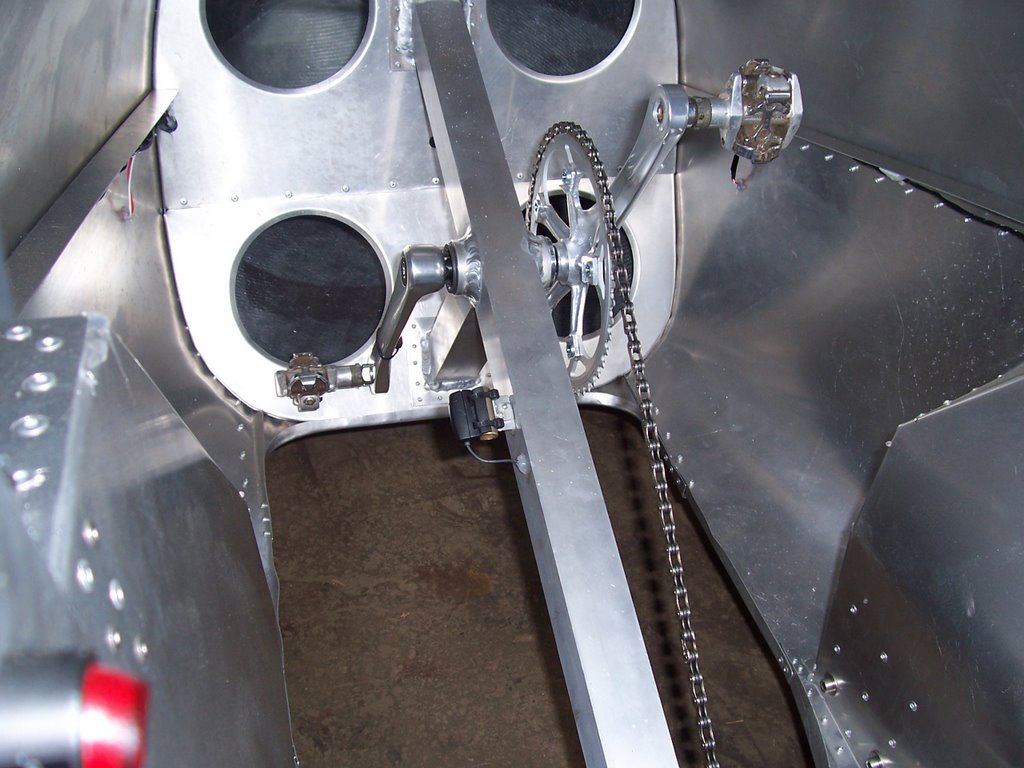
The drivetrain, wiring and electrical components are all installed. I even spent a whole day designing, fabricating and installing brackets to mount the pick ups for the cyclo-computer. One for speed at the right wheel, and one for cadence at the crank. I ran the cadence wiring right through the square tubing. Since the square tubing is too thick for the grommets I used to protect the wiring where it passed through the sheet metal, I sealed around the wires with RTV silicone sealant. (clear) I also had to do this for the turn signals, since the design of the LED's would have placed the grommet in a position which would have prevented proper adhesion of the sticky back mounting system.
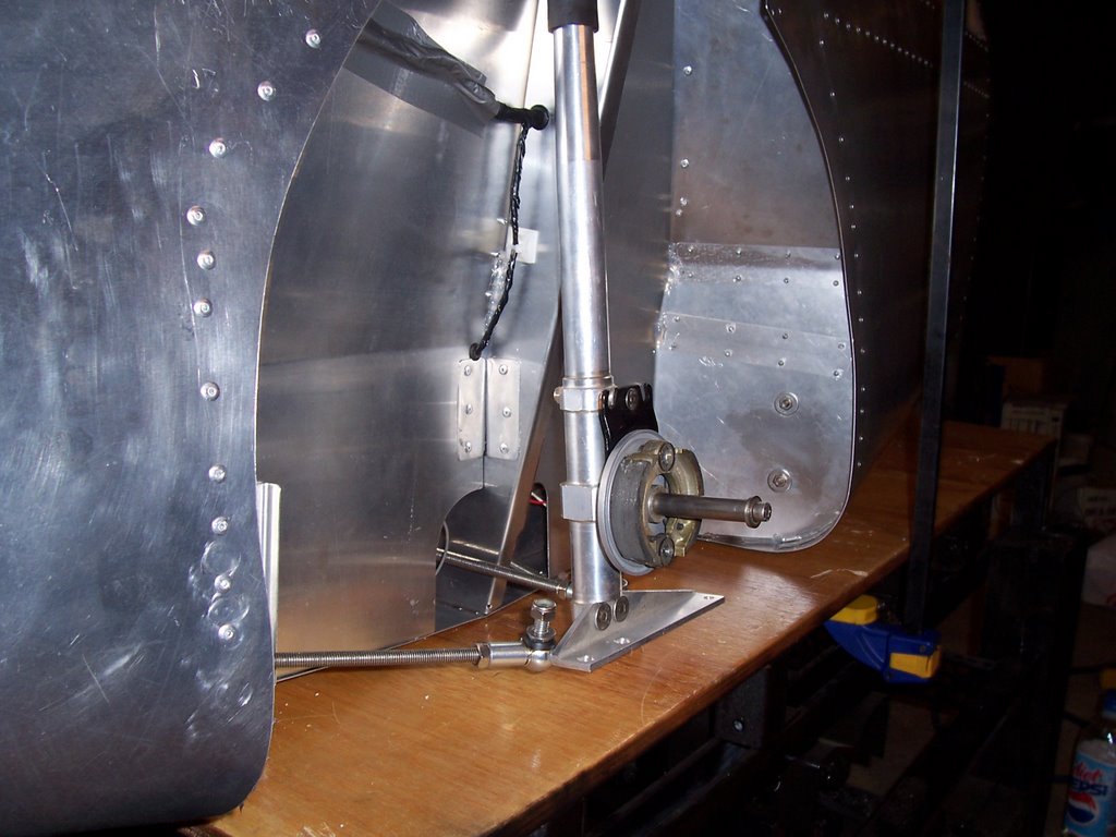
Above left is the right front shock with steering linkages, and brake shoes.
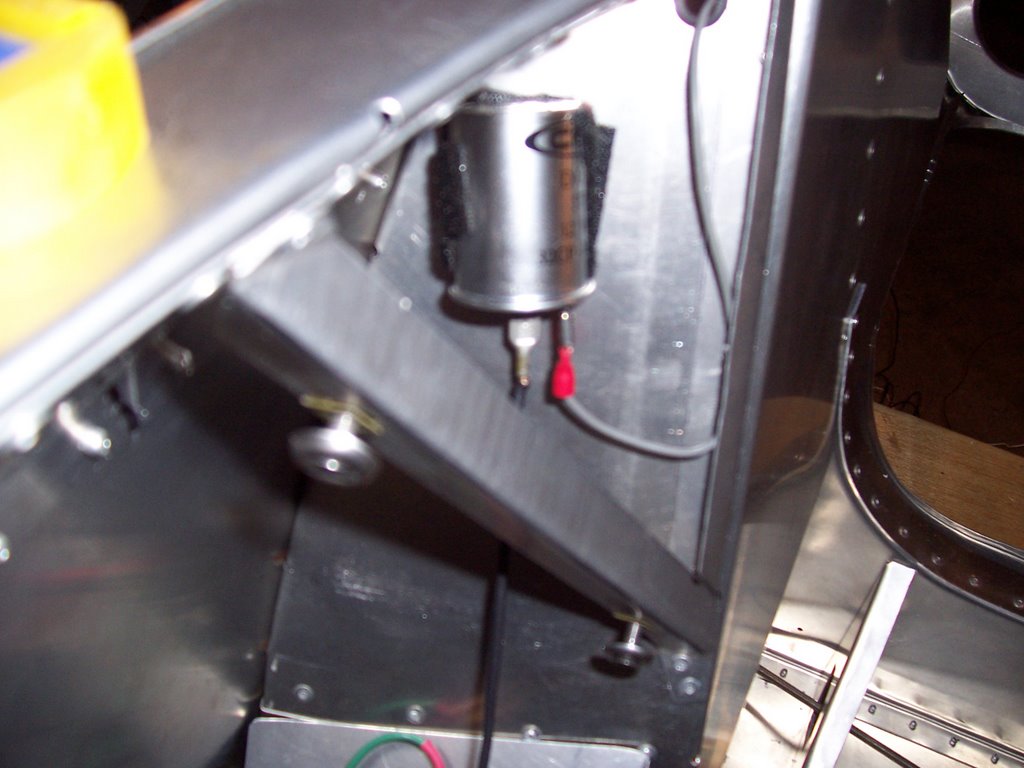
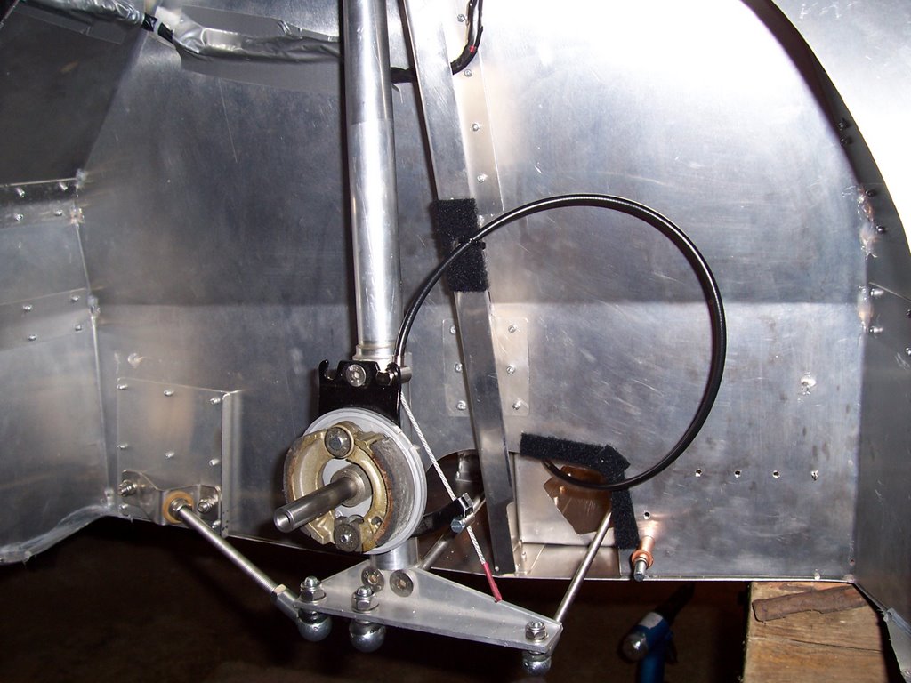
I used vecro at the attachment point of the brake cable, and also where it passes through the wheel well, for protection. I also used velcro to attach the flasher. I found that the LED turn signals didn't draw enough current to make the flasher work, so I stole the front turn signals from Aunt Anne's old car, and used them to operate the flashers, and act as turn signal indicators. Since they were dual filament, I was also able to add another switch, and use them for interior lighting as well. I used velcro to attach them, making it easy to remove for bulb replacement.
As seems to be the routine, the next batch of photos failed to upload, so I will attempt to publish what I have so far, and come back at a different time.
posted by VMDave at 4:20 PM
![]()
![]()

0 Comments:
Post a Comment
<< Home