Sunday, March 26, 2006

News from afar...

I just talked to David Eggleston on the phone. He contacted me through the internet. Cool. Anyway, He gave me enough information to calm my fears that I had put things together wrong, and many helpful suggestions as well. He also informed me that he is working on nosecones, and should return to Texas with the skills and molds to produce them here in the US.

In my last post, I was discussing the constuction of the seat, and if the blogger is cooperative and allows me to upload some photos I will continue doing so.

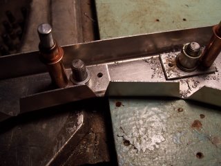
Cool. This photo shows the seat clecoed together, after which I took it all apart, and deburred all the holes. This step, while tedious and time consuming, is very important because failing to do so would result in chips being trapped between the parts being riveted together. The sharp edges present in un-deburred holes also add to the stress applied to the rivets, since they expand somewhat to fill the holes in which they are used. Any sharp edge or corner creates a stress riser, which weakens the assembly. Even the steps turned in a steel shafft are made with a radius rather than a square corner to minimize this effect. But I digress....... How about another picture?


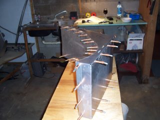
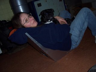
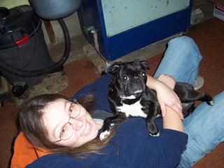
The photo above shows the seat all riveted together, and ready to be comfort tested. To insure impartial results for this test, I enlisted the aid of my fiancee, Leah. She is shown below actually testing the seat, while making herself look even more beautiful by holding her ugly little dog (Lola).


Now I guess I need to take some more pictures. I haven't yet finalized placement of the battery packs and associated equipment for the Power assist option. I am thinking about making brackets to hold the batteries down with elastic or perhaps O rings. Wow, Leah just suggested velcro....I like it. Thank you Leah. Well I am happy that the old bloggerbot was willing to upload my pictures today. The last few attempts have been frustrating at best. Besides thinking about battery placement and retention I have been trying to work up the courage to start the next phase of assembly. I have clecoed things together and studied how they will come together. Having done so enabled me to ask David some important questions, and so I am ready to move forward once again. More in a few days...

Monday, March 20, 2006

Have a seat...

David Eggleston is away in the NL, and while he has not yet completed the new instruction manual, he did take the time and trouble to snail mail me a copy of the original Dutch version before he left. Since the version of the Alleweder produced by VM USA is so different than the original Flevo model, the manual is somewhat obsolete. However, it still gives a good overview of the construction, with lots of diagrams, and also reveals how much easier the US version must be to assemble. Many of the holes are predrilled at the factory in a computerized machine, which saves hours of lay out time. In some cases, a couple of allignment holes have been drilled, so that parts can simply be clecoed in place, and drilled through the factory holes into the appropriate structural member.

I ordered my kit with the Power Assist option, and some items for that arrived this past week. Four 24V battery packs, a smart charger, watt meter, and the battery cut off switch. The switch had to be ground flat top and bottom, and radiused to fit in the U channel. I need to get some 5MM nuts and bolts (preferably stainless steel) to complete mounting the switch. In the back ground, you can see a diagram of the seat mounting bracket in the Dutch manual.

I really want to wait for the step by step instructions before continuing with the main body, but felt comfortable constructing the seat using the diagrams from the Dutch manual.

The first step was to drill the 1/8 inch holes in the sides of the seat out to 8.5MM to accommodate an 8MM bolt, and rivet in nut plates. The bolt is a convenient means of clamping the nutplate in place for drilling the #30 rivet holes. Then, after deburring, the nutplate is clecoed in place and the bolt is inserted to verify proper positioning.

Next, the back of the seat is attached to the side plates. This is done first with #40 clecos, in a few places to ensure allignment, then with the #30 rivet sized drill. The front plate of the seat was a little different, because of all the curves. I simply clecoed the front in place, then worked my way up, drilling and clecoing each hole in turn to force the front plate to conform with the shape of the sides. I have lots of detailed photos of the process, but the stinking Blogger isn't uploading them. At least today's attempt got two more than yesterday's. I guess I'll try again tomorrow....sorry.