Monday, June 26, 2006

Maiden Voyage...second trip


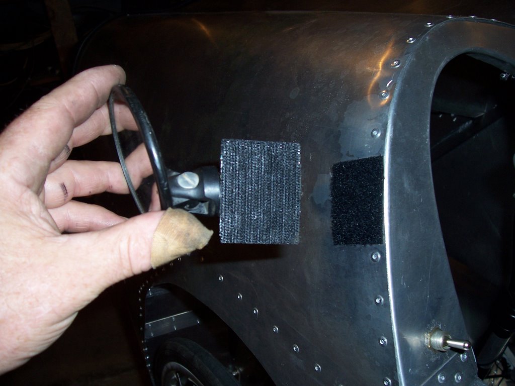
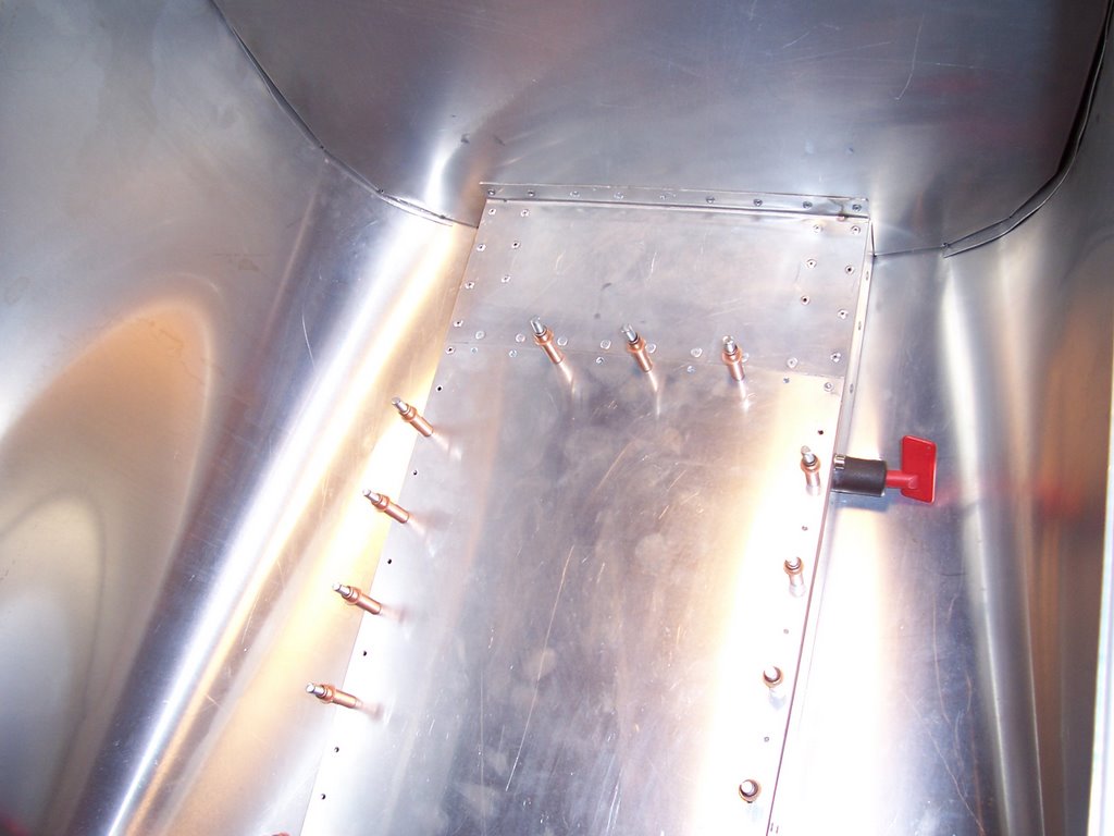
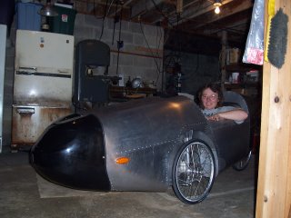
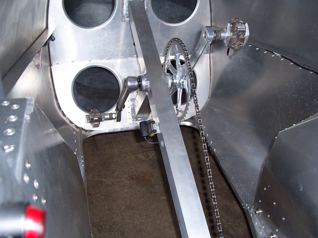
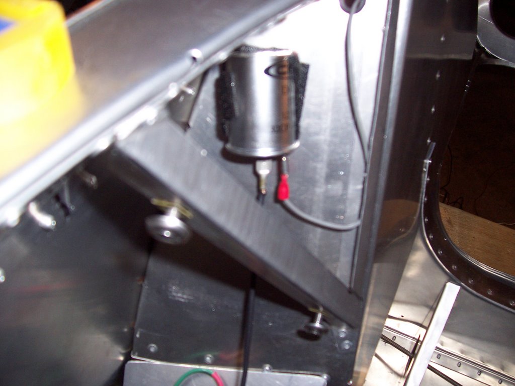
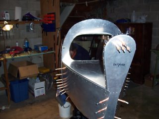
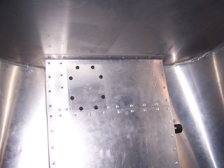
After searching for hours out in the garage, I finally located an old Third Eye mirror,that mounted in the end of a mtn bike bar. While thinking about a way to mount it, I found some plastic clamps to attach the mirror to an aluminum plate, and thus velcro it onto the Alleweder. I don't have the canvas cover yet, so I didn't want a permanent set up, but still needed a mirror.

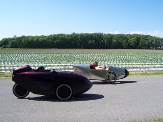
With the temporary mirror in place Leah and I were off for our first velomobile ride together, she in the Alleweder, and I in the Versatile. It was just an 8 mile ride to Hamburg and back, but on the way back, Leah complained of poor shifting, and strange noises. Upon inspection, I found that the upper chain tube (the one mounted in the floor) had come loose, and was caught under the idler sprocket just aft of the chain ring. I removed the idler, the rear wheel, and took the chain apart to remove the chain tube for inspection. After straightening it out, it was serviceable enough to use, but I decided to make an access hole at the rear attachment point, so this problem could be dealt with on the road if necessary. I drilled out the rivets in the back piece of floor and cut out the area I wanted to get at, using sheet metal screws to attach a plate over the hole.


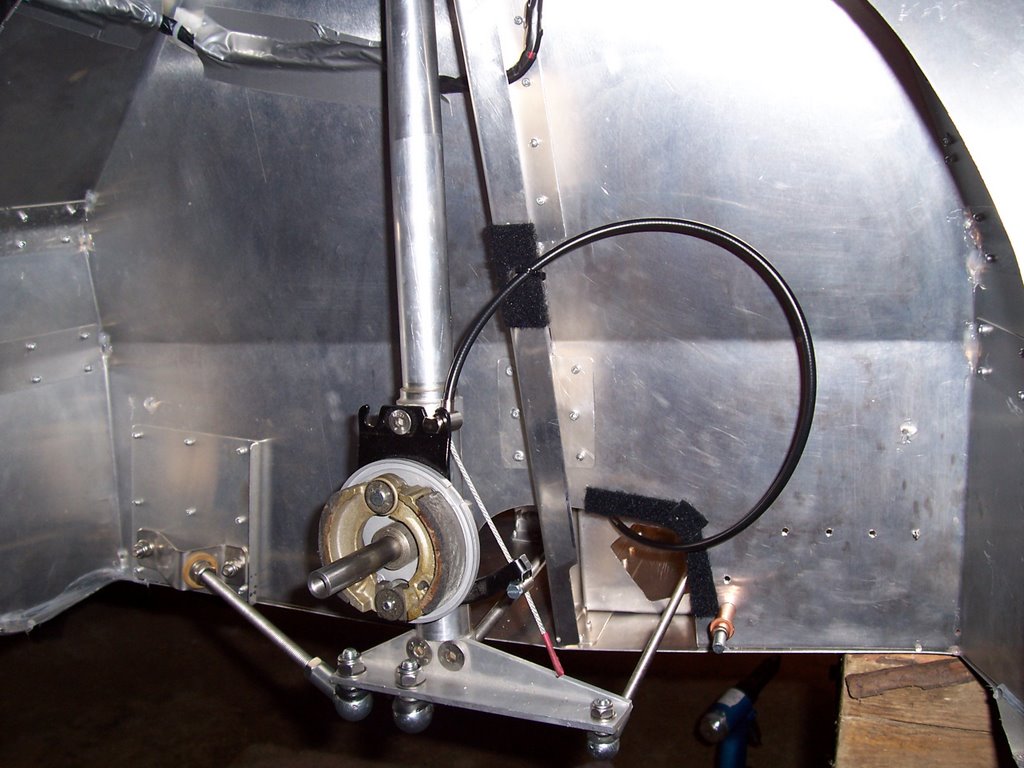
I did rework the mount for the chaintube, and have hopefully corrected the problem, but it's good to know that I can now deal with it on the road if I need to. The other problem that occurred on the maiden voyage was that when Leah clipped out of her pedals she inadvertantly popped the hood by bumping it with one of her shoes. I was able to get it back down, but it has some wrinkles in it now. I am thinking that if it continues to be a problem, I will make up a bracket to tie the middle of the hood to the square tubing, and put in a few rivets sealed with RTV. I also popped the right brake cable on the Versatile while we were out. My previous experience with the shifter problem I had had left me prepared for this repair,which only ended up taking about half an hour. While the brake handle was off, I took the time to chamfer the hole where the cable exits the brake lever to extend the life of the next cable. It was nice to find that the reversing wheel which enables either brake handle to operate both brakes simultaneously also allowed me to stop the Versatile with one cable broken. Nice design.


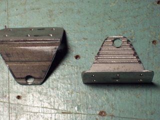
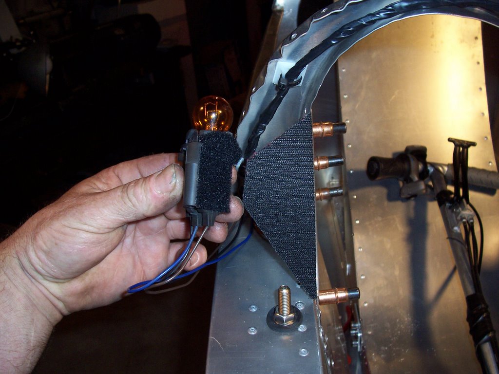
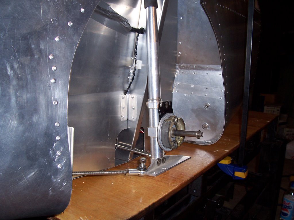
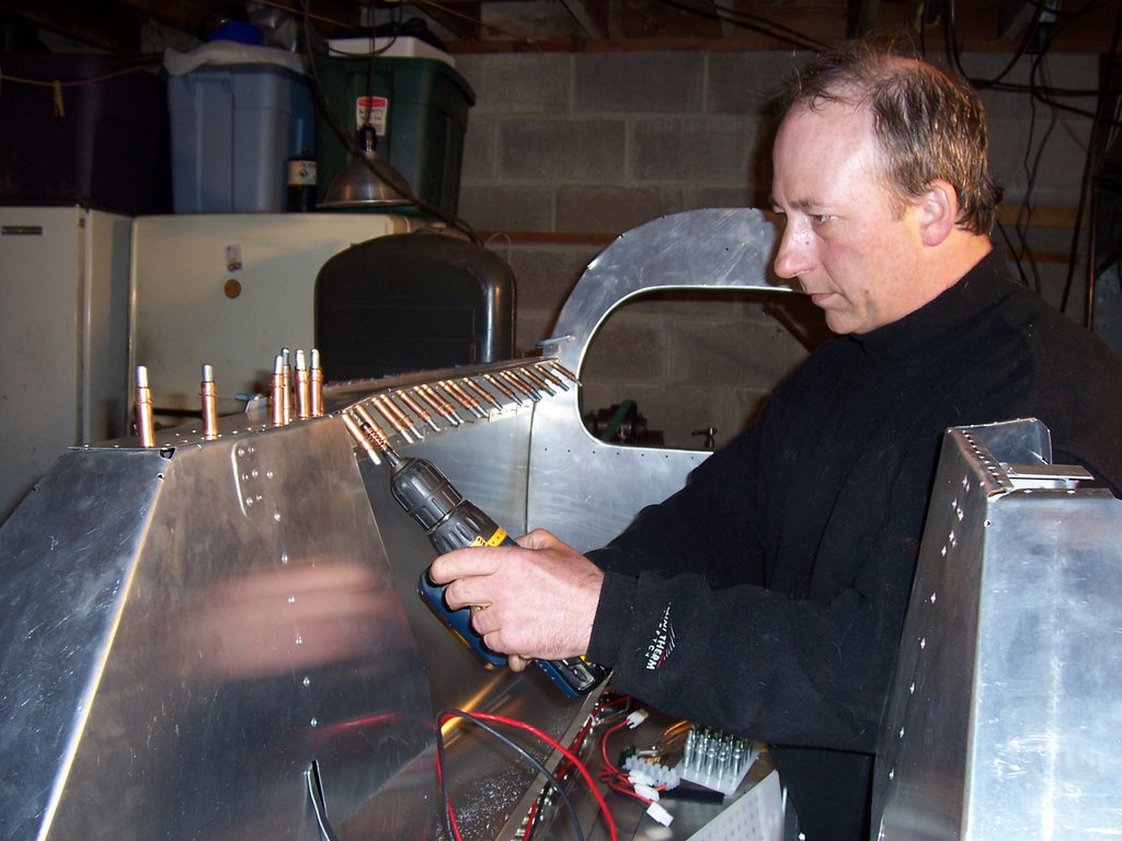
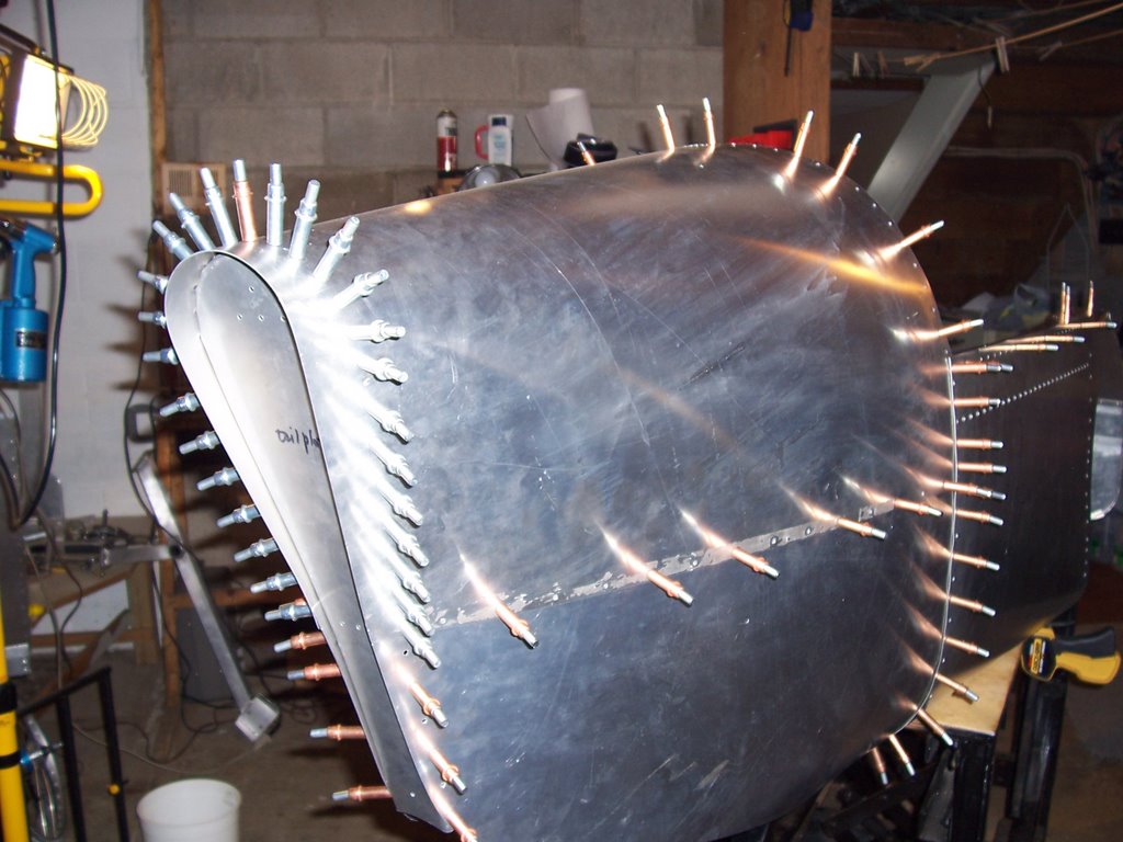
Since I had had such good luck with velcro, I decided to make up a temporary headlight mount outside the nosecone. I started off by making these angle brackets from an old piece of screen door. I used the lathe to center drill,and tap a plastic dowell to go between the brackets, and mount the light to. I then cut a piece of Al. to rivet the brackets to, and attached the 2" sticky back velcro hook material to the bracket. I used the loop material on the nosecone, and drilled a hole for the wires that was in a location where it would be removed anyway if I decide to mount the lights inside behind the plexiglass. Actually, this "temporary" set up looks kind of neat, works well, and I have to believe that the lights are much brighter mounted on the outside.


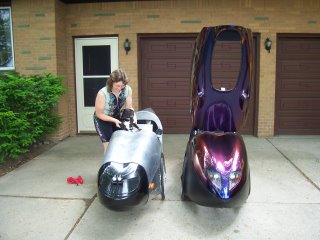
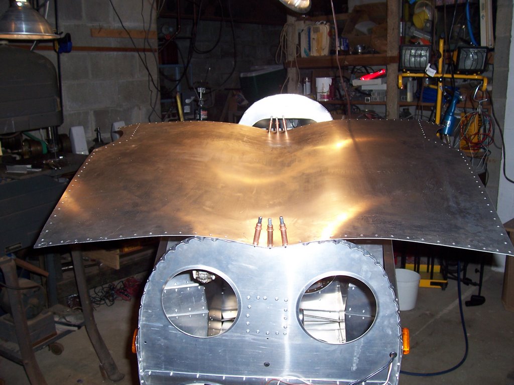
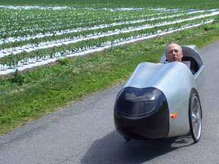
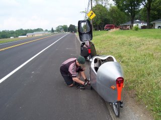
Here you can kind of see the finished light mount as we prepare for a trip into Eden, with canine passenger.


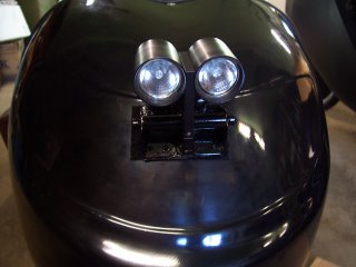
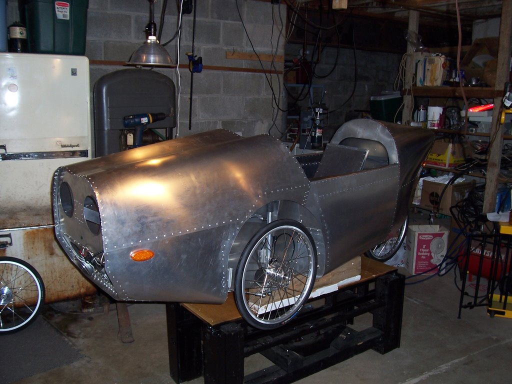
Perhaps this is a little better view. The second ride had no chain tube or hood problems, but we did get a flat tire. No biggie, I had several spare tubes, and a pump in the Versatile. Tools aren't even really necessary, because the front wheels don't need to be removed to change a tube or tire.
Well, I guess that catches us up for now. I will post new developments, repairs, improvements, etc. as they occur. I have also begun a blog on my Versatile, starting with my trip to The Netherlands. It can be found at: http://snapmobile.blogspot.com .

almost done.....


Here's one of the stolen turn signals. Velcro is great stuff. I plan on using it to restrain the batteries for the power assist, but since the motor and controller are not yet available, I cut foam blocks to fill in where they will fit in the floor.


I also cut the floor in three pieces. The location of the cut out for battery access in the original design didn't really fit my layout, so I ordered a couple pieces of aluminum sheet from MRC, a supplier for work. I put splice pieces between the cut out center section and front and rear sections, so that structural integrity of the floor would not be comprimised, while full battery access will be available by drilling out some rivets. I won't have to mess with the long ones in the back, or the front section where there are rivets in all different directions. This worked out well, because I found that after attaching the nose section, the front part of the floor was too big to fit between the wheel wells. I was able to flatten out some previous bends, cut deeper notches at the corners, and rebend the piece to fit properly. It was challenging, but worked out well.

I had already drilled and clecoed the hood, and removed for deburr and wiring, but was dissatisfied with the rough sketch manner in which I had marked the section of wheel well cover that needed to be cut out. The dutch manual gave a radius to use for the arc. I used their figure to create a template that fit perfectly, and enabled me to cut the pieces out on the band saw with minimal filing. Sweet. I also marked and cut off a little extra metal from the area at the dashboard, and a little bit from the right front of the nose. I must have been off a little bit on the initial placement of the wheelwells. This made assembly more difficult, and the whole thing is a little crooked, but I was still able to fet it all together.


Rivetting is the easy part. Once everything has been drilled, deburred, and re-clecoed in place it goes very quickly.


The next step was the nose cone. David E. from VelomobileUSA did a beautiful job on it. It comes with preglued rubber edging which takes a little while to install, but stays where you put it, and looks and works great.


Here's Leah checking it out. I had to have her sit in it while I adjusted the steering linkage to make the wheels equidistant front and rear. First you adjust the wheels to tilt in at the top, then center them in the wheelwell, then the steering. I used a large Irwin bar clamp to set the steering. Having seen the guage they used to set up my Versatile in NL. made me think of using it right away.


Everything functioned well on the first test ride. I was shocked at how much more quickly the Alleweder accellerates than my Versatile.( which costs a whole lot more) The test ride did however demonstrate the very immediate need for a mirror. My next post will show what I came up with from what I had laying around out in the garage, the maiden voyage (and subsequent repairs) and the temporary headlight mount.

Saturday, June 24, 2006

progress...


The drivetrain, wiring and electrical components are all installed. I even spent a whole day designing, fabricating and installing brackets to mount the pick ups for the cyclo-computer. One for speed at the right wheel, and one for cadence at the crank. I ran the cadence wiring right through the square tubing. Since the square tubing is too thick for the grommets I used to protect the wiring where it passed through the sheet metal, I sealed around the wires with RTV silicone sealant. (clear) I also had to do this for the turn signals, since the design of the LED's would have placed the grommet in a position which would have prevented proper adhesion of the sticky back mounting system.

Above left is the right front shock with steering linkages, and brake shoes.

I used vecro at the attachment point of the brake cable, and also where it passes through the wheel well, for protection. I also used velcro to attach the flasher. I found that the LED turn signals didn't draw enough current to make the flasher work, so I stole the front turn signals from Aunt Anne's old car, and used them to operate the flashers, and act as turn signal indicators. Since they were dual filament, I was also able to add another switch, and use them for interior lighting as well. I used velcro to attach them, making it easy to remove for bulb replacement.

As seems to be the routine, the next batch of photos failed to upload, so I will attempt to publish what I have so far, and come back at a different time.

Thursday, June 22, 2006

Tail section


Upon looking into what it would take to install the tail section, I realized that I would need to drill out the rivets I had installed in the one cockpit sideplate. Not too big a deal, but first, I installed the armrest supports, since the armrests are pretty flimsy without them, and I didn't want them getting all bent up.

As you can see, I use alot of clecos to keep things lined up prior to riveting. It's pretty amazing what you can do to a flat sheet of aluminum. I started at the top, and kept drilling holes and clecoing the top tail sheet in place till I had created this porcupine-like structure.If I ever build another kit, I will definitely purchase an air powered cleco gun. Using the standard pliers leaves your hands pretty tired at the end of a day's work.


Here's a shot of the tail side plates without the top plate. The baggage compartment floor is visible at the seam of the top and side plates. Unfortunately I didn't get photos of the installation of the rear swing arm and rear shock, with the doubler that needed to be installed under the top shock mount bracket. Most of the time I have been ahead of the instruction manual, and the biggest hold up I have had has been trying to figure out what to do next, and the best way to make it all fit together. Having a complete assembly manual from the start would have made the process much faster and easier. To date the manual only is as far as the tail, and the version I was working with was missing some text and photos that were stacked on top of each other.


None the less, I continued, installing the bottom bracket and the square tubing that replaces the sheet metal box used on the original version, front bulkhead, and nose sideplates.


The lower nose plate was also installed at this time. Then I installed the cranks, the rear wheel( I had been waiting for the cassette) the chain, and the 2 chain tubes. One of them goes inside the floor, and the other under the body. Things really started moving along at tis point. The steering rod was installed, along with the front shock struts, and steering linkages .At the same time, I was installing various wiring and lighting system components. Turn signals, flasher, tail lights, and horn. Much of the wiring for these components ran through the wheel wells, and as such, needed to be installed before the shocks.

Well, I just uploaded 5 photos but they aren't here, so I think I'll continue at a later date.